Leak Test Procedure
Quantifying unintended gas loss in a system using the pressure decay method. The system is pressurized, isolated, and monitored over time; any pressure drop indicates a potential leak.
About this task
This procedure describes how to perform a pressure decay leak test to verify the integrity of a gas system. For background information on how this test method works, see Pressure Decay Leak Test.
Procedure
-
Assemble the system according to the subsequent lab operation. Cap the outlet of the device under test.
Not all components of the system need to be leak-tight—only the leak-critical parts must remain unchanged after the leak test. For example, in mass flow calibration, only the section between the reference and the device under test is critical; components before and after this section can be modified once the leak test has passed.
Figure 1. System Setup 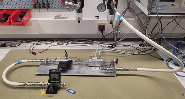
-
Ensure that internal system valves—such as the MFC bypass valve—are opened so the entire system is pressurized.
Figure 2. MFC Bypass Valve 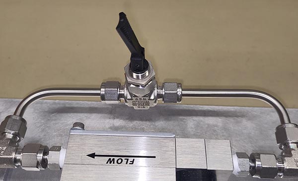
-
Apply the test pressure, which corresponds to the maximum process pressure expected during the subsequent calibration (typically 2.7 bar A for Molbloc-L calibrations or 5 bar A for sonic calibrations).
CAUTION:The pressure gauge on the regulator shows relative pressure. The leak test specification is always in absolute pressure.
Figure 3. Supply Pressure 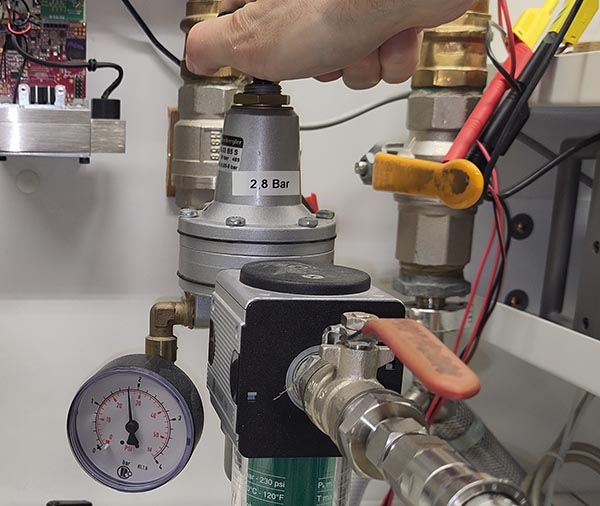 Although the pressure reducer includes a gauge, it is recommended to confirm the absolute pressure using the molbox by pressing P/T.
Figure 4. Molbox Pressure 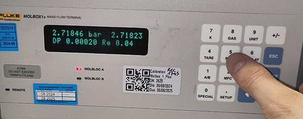
-
Isolate the system by closing the inlet valve (down position).
Figure 5. Close Inlet Valve 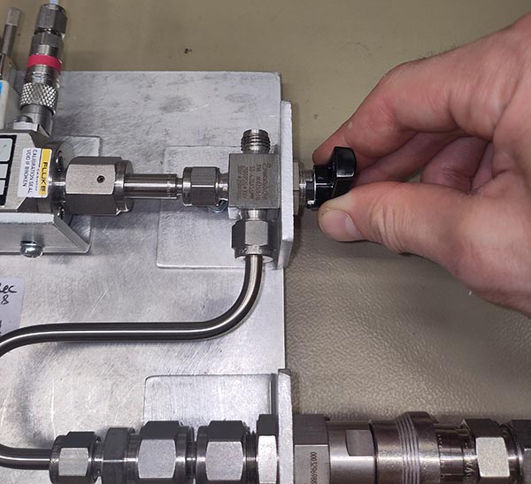
-
Open the Service Tools software and click on Leak Test in the ribbon.
Figure 6. Leak Test Utility 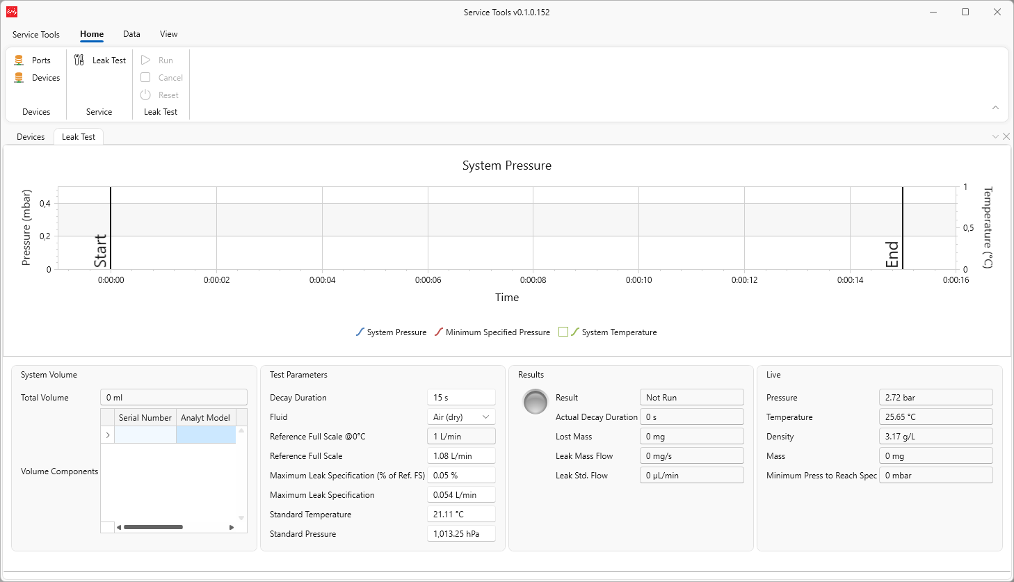
-
Use the barcode scanner to scan every piece of equipment contributing to the internal system volume.
Figure 7. Scan Test Rig 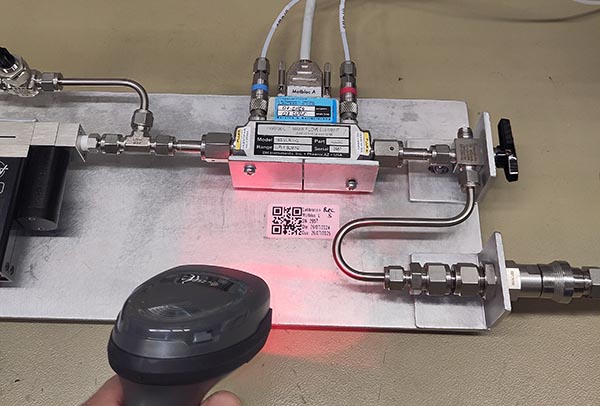 The software will query each component in the database and calculate the total internal volume of the system.
Figure 8. Volume Calculation 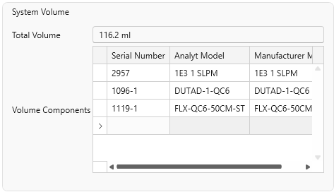
-
Set the decay duration, fluid type, and maximum allowable leak rate according to the required uncertainty for the upcoming calibration.
The system starts with a default leak rate specification based on the full-scale flow of the selected molbloc and a predefined percentage. However, all parameters can be manually adjusted.
Figure 9. Test Parameters 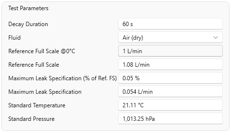
-
Click Run to start the test.
The system will automatically record and plot pressure over time, and calculate the minimum pressure threshold below which the system must not fall to meet the test specification. This is useful for visually determining if the test is likely to fail, allowing the user to cancel early and address the leak.
Figure 10. Decay Run 
-
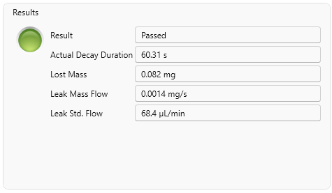
Review the test results.
Once the test is complete, the results are shown in the Results section. This includes a clear indication of whether the test passed or failed, as well as key metrics such as the actual decay duration (always equal to or longer than the configured duration), the mass lost, the leak mass flow rate, and the standard volumetric leak flow—calculated at the standard temperature and pressure defined in the test settings.
Figure 11. Results